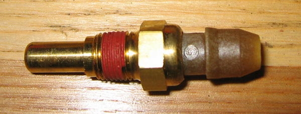
The IAT sensor is a thermistor – that is, it’s a resistor that changes resistance with temperature. The resistance level tells the PCM the coolant temperature. The ECTS (engine coolant temperature sensor) and the IAT (Intake Air Temperature) sensor are the same part.
The IAT
(brass tip – may also be resin tipped & more rounded)
New IAT (brass or resin tip should work fine. The brass tipped is highly recommended for use for the ECTS, but the IAT does not get put to the same abuse, so either style works fine)
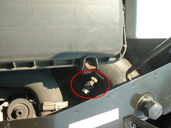
Location
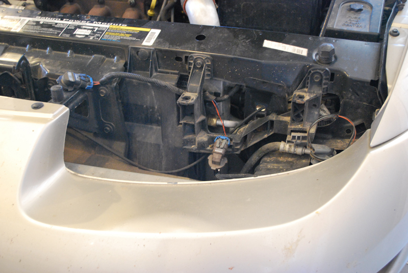
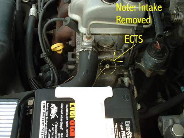
On most S-Series, the IAT sensor is in a tube in front of the air filter box. As you’re standing in front of the car, look at the corner of the air filter box to the right & close to you. The tube comes from this corner, and the IAT is screwed into that tube.
Replacement
Step 1
Remove the wiring connector. Use your fingers or the needle nose pliers to squeeze the connector, releasing the tabs. Gently pull the connector from the sensor.
Step 2
Unscrew the IAT using the 13mm socket or wrench. Loosens counterclockwise (normal thread direction).
Step 3
Install is reverse of removal. No need to tighten very tight.
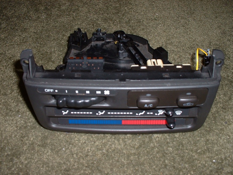
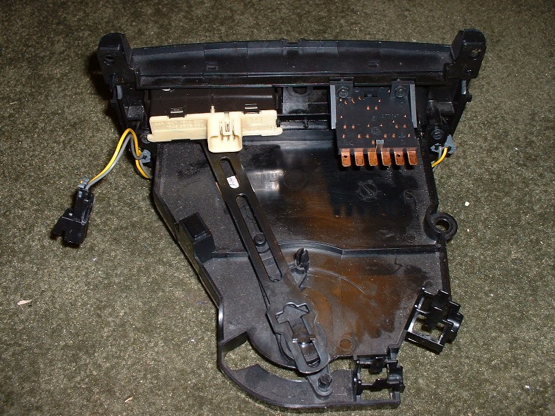
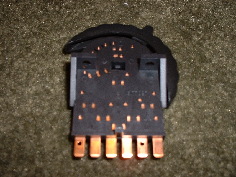
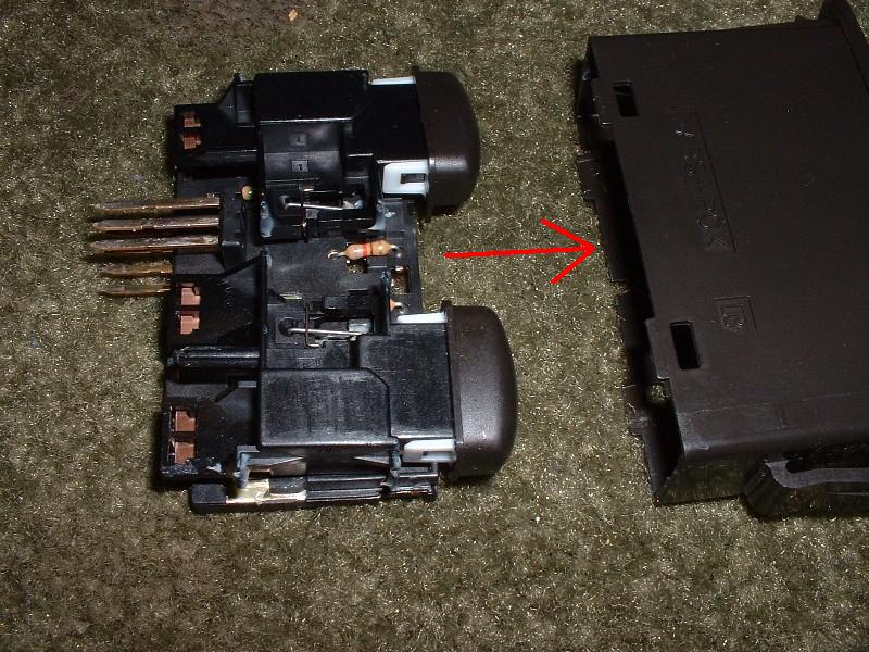
Remove the two 1/4″ screws (I have no idea why these aren’t metric like the rest of the car) and remove the switch out the back of the HVAC control panel.
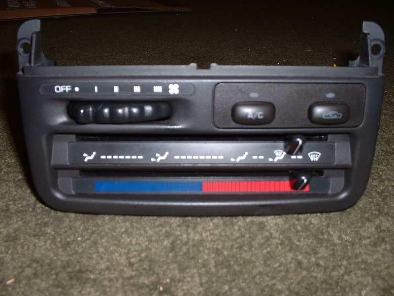
Fan control switch:
Dismantle Fan Control
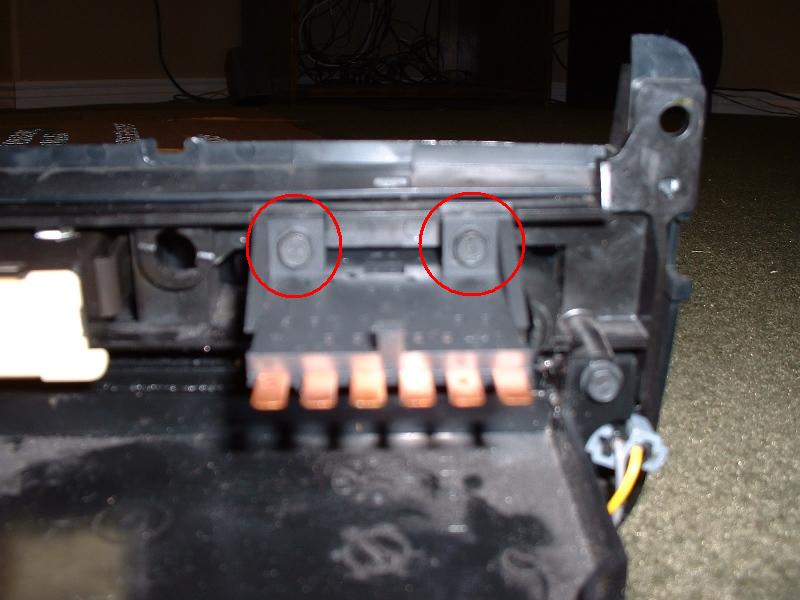
Step 1
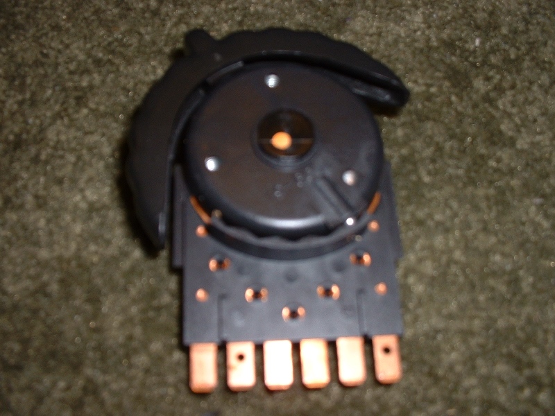
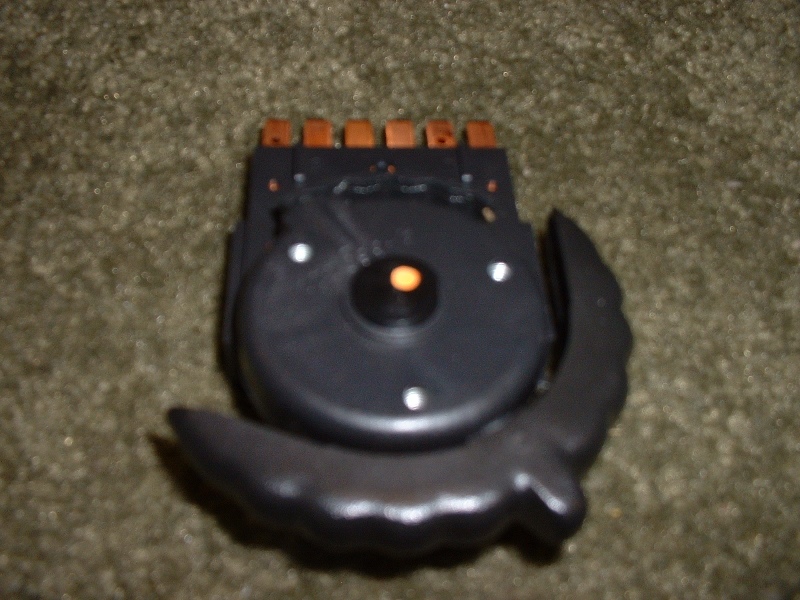
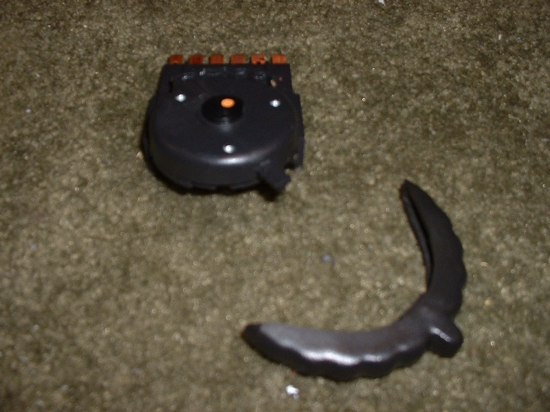
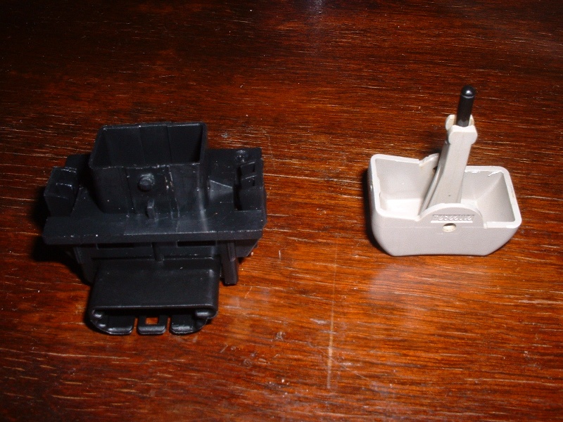
Remove the curved switch. Just pull straight out.
Step 2
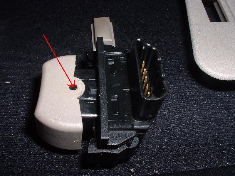
Remove center retaining pin. Squeeze the two tabs together from the top of the switch assembly (can use a small flathead screwdriver, or some needle nose pliers) to release the pin. Get ready to catch small parts!
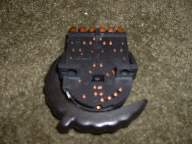
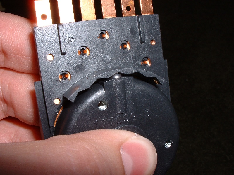
Resulting Parts
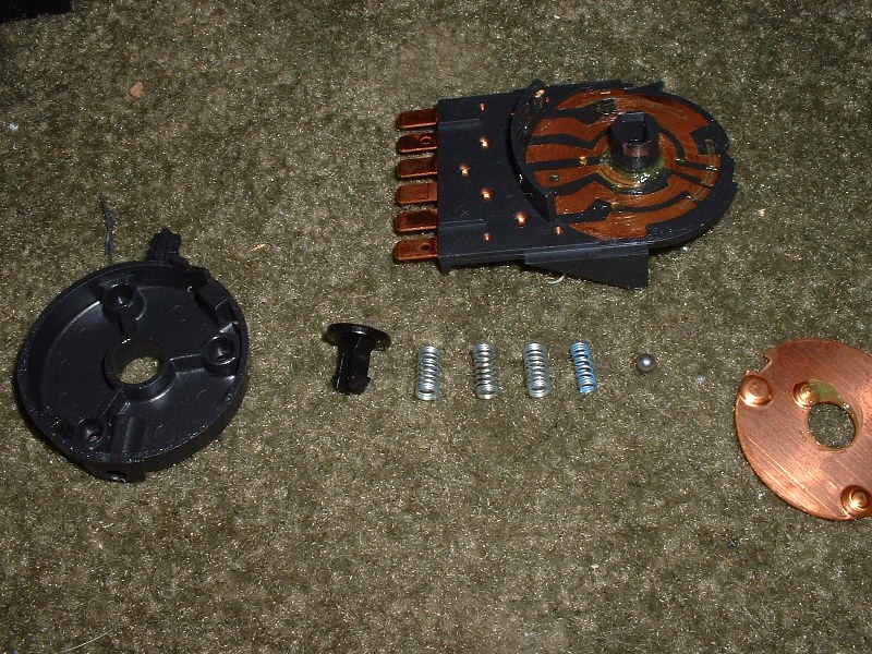
Resulting parts: -3 identical springs -1 smaller spring -plastic pin/clip -ball bearing -metal disk -plastic disk/housing -base with circuit board
Reassemble Fan Control
Step 1
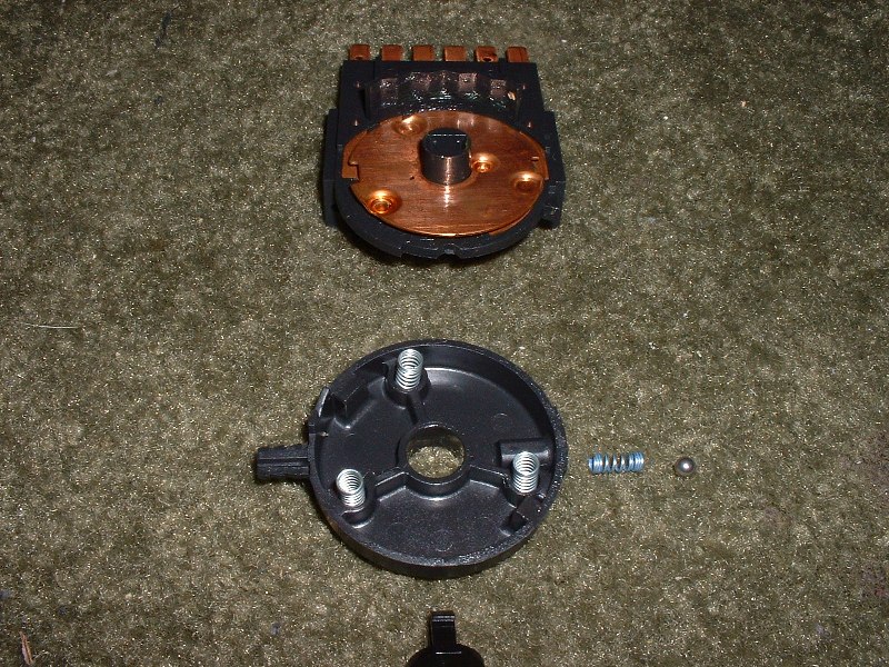
Place 3 larger springs in the plastic disk. There are round indentations for them. You do not need to place the metal disk on the circuit base yet, despite it being there in the picture.
Step 2
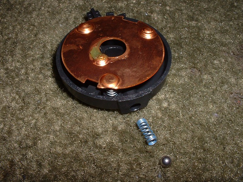
Place the metal disk on top of the 3 springs. There are round indentations for them on this disk as well. Also pay attention, as there are notches in the metal disk that line up with parts of the plastic disk.
Step 3
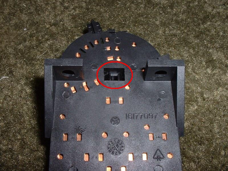
Place smaller spring and ball bearing into the plastic disk, and place the assembly onto the circuit base. There is a hole in the side of the plastic disk the spring and ball go into, as seen in the picture above. The spring goes in first. You will have to hold them in place while you carefully slide them onto the circuit base, with the ball nesting into the notches as seen below.
Step 4
Insert the retaining pin into the center of the plastic disk. It should click into place.
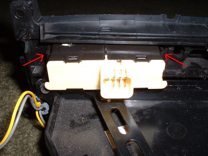
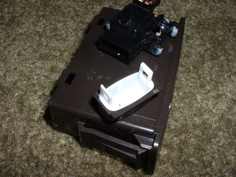
Remove AC and Recirculation Buttons
Step 1
Squeeze the tabs on each side of the assembly. You can probably do this with your fingers. If not, a good size flathead screwdriver will make it an easy job.
Step 2
Slide out the front of the HVAC control assembly.
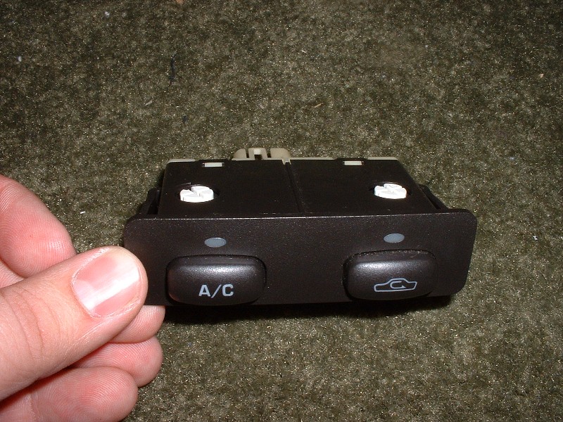
AC/Recirc button assembly:
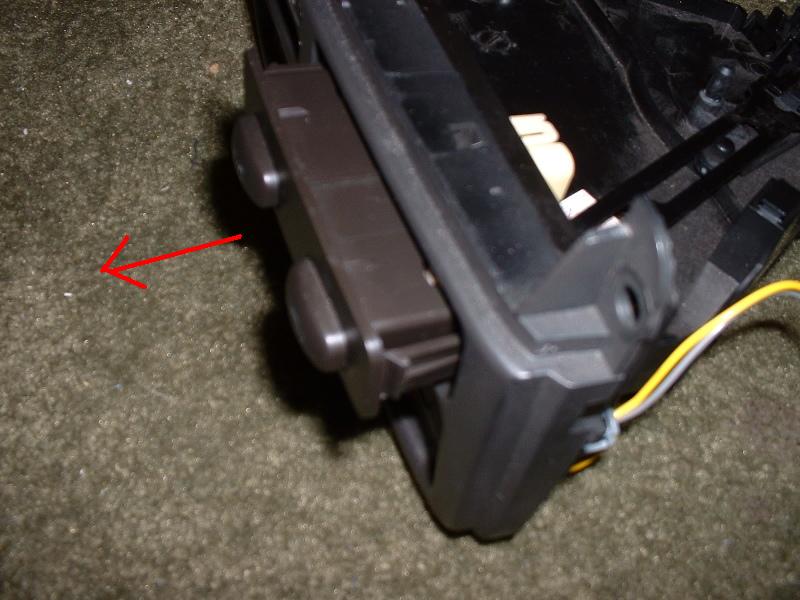
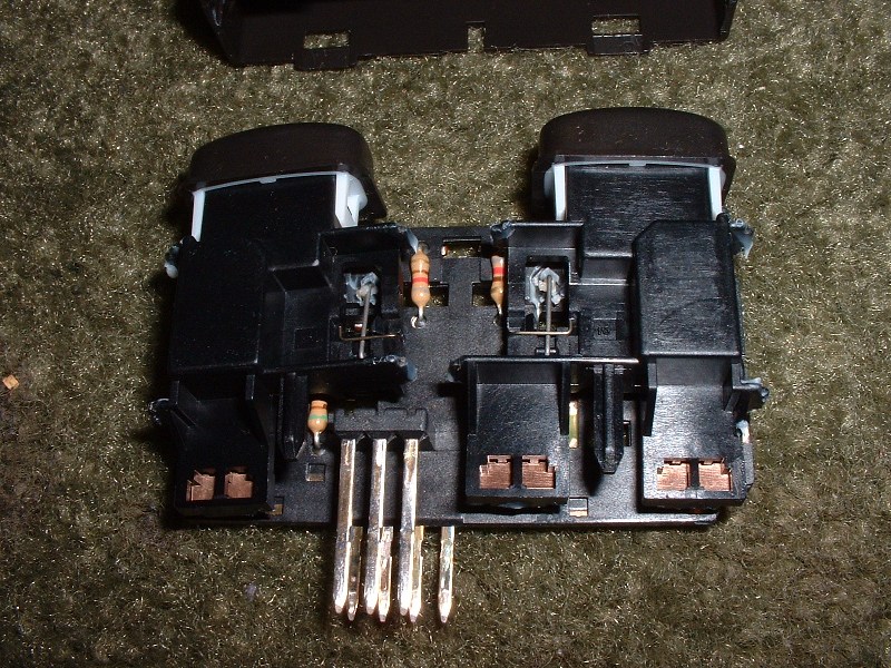
Remove AC/Recirc Buttons from Housing
Step 1
Remove light bulbs. Use a flathead screwdriver and turn the bulb about a quarter turn.
Step 2
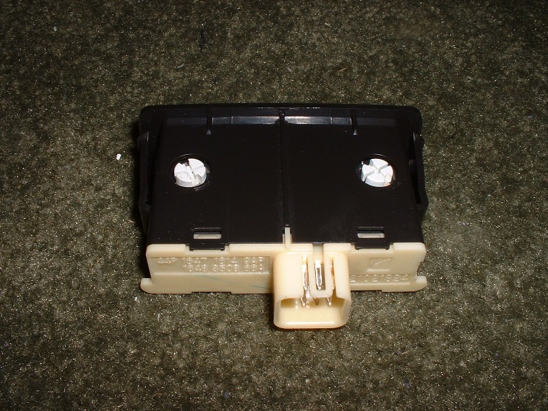
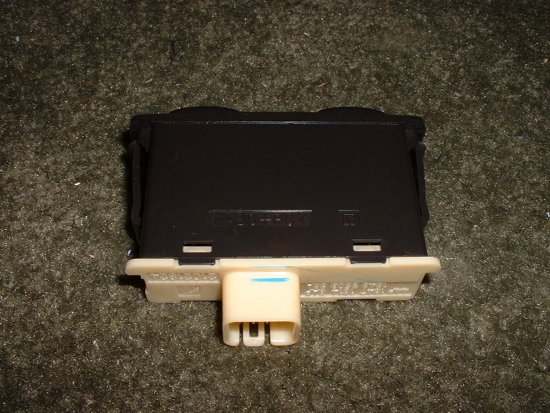
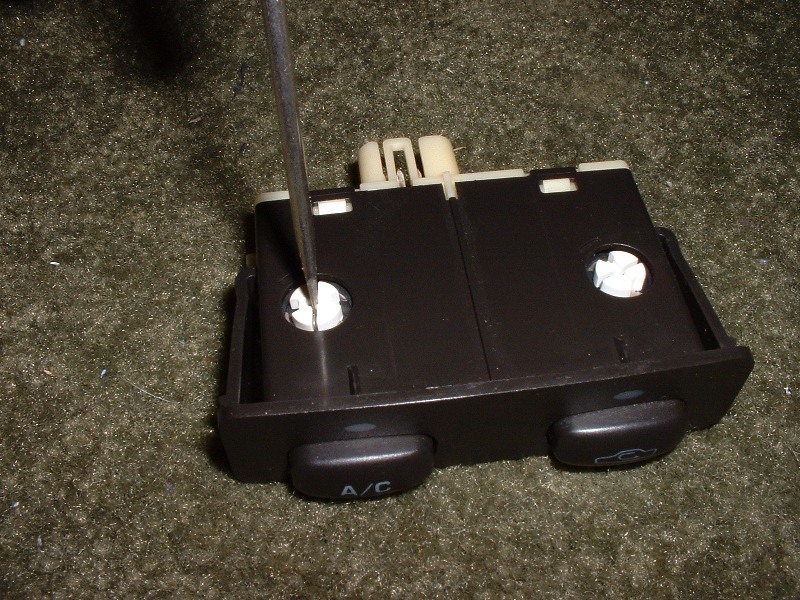
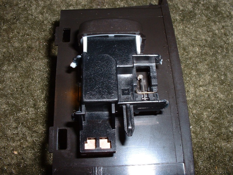
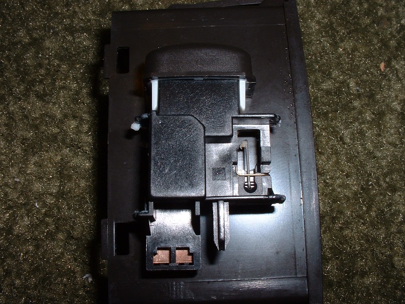
Remove the rear face. Use a flathead screwdriver to gently pry the tabs loose, and pull the rear face off, being careful of the wiring harness pins. (Assembly propped up in pictures by a screwdriver for better pictures)
Step 3
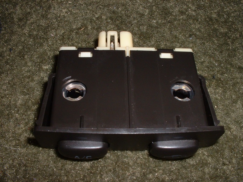
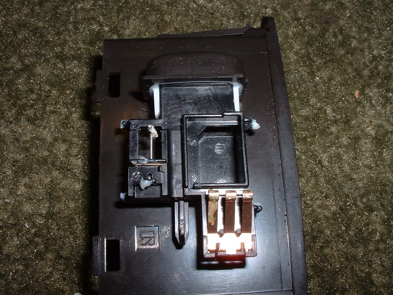
Remove the buttons from the housing. Remove the two springs from the back of the assembly. Then press in on the buttons to start pushing the innards out of the housing. Then as you can reach the base of the innards, pull it the rest of the way out.
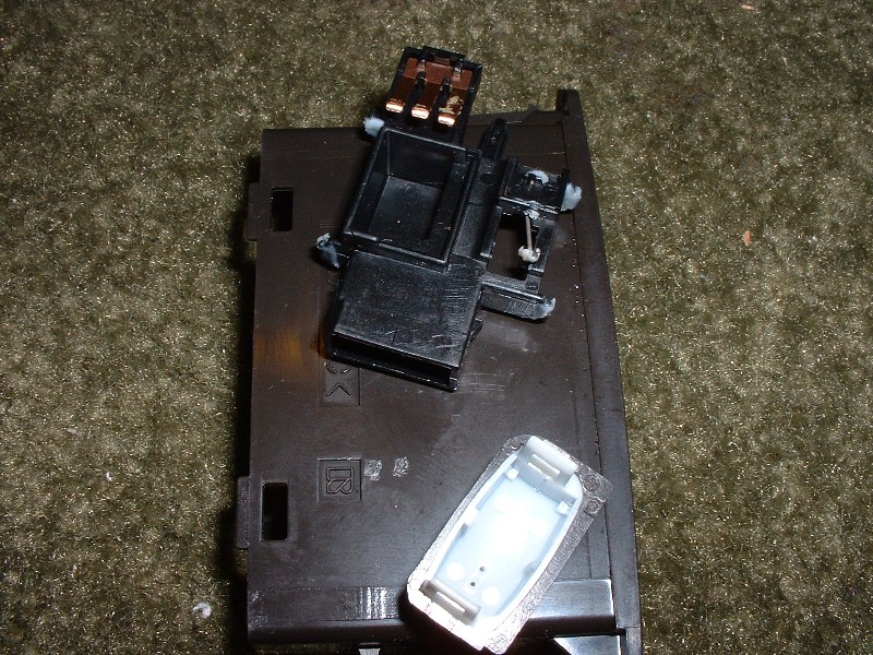
Step 4
Remove the buttons. They just lift off. The button face can be popped off with a small flathead screwdriver – there is a tab on each side of the button. (shown resting on top of the housing to keep carpet fuzz out of the lubricants on the buttons)
Reassemble AC and Recirculation Buttons
Step 1
Place the button assemblies on the base plate. Make sure the small wire spring is resting in its track. If you hold the switch down against the plate, you should be able to click the button in and out properly to ensure the spring is positioned correctly.
Step 2
Push the parts into the housing.
Step 3
Push the parts into the housing.
Step 4
Click the rear back into place. Make sure the two springs seat on the bumps on the back of the housing, and that you do not bend any of the wiring harness tabs.
Remove Slider Light Bulbs and Wiring
Step 1
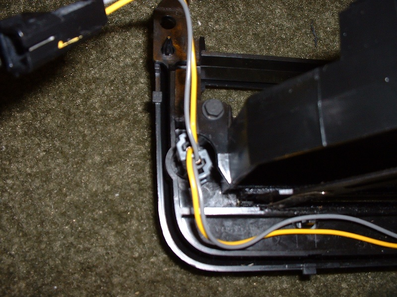
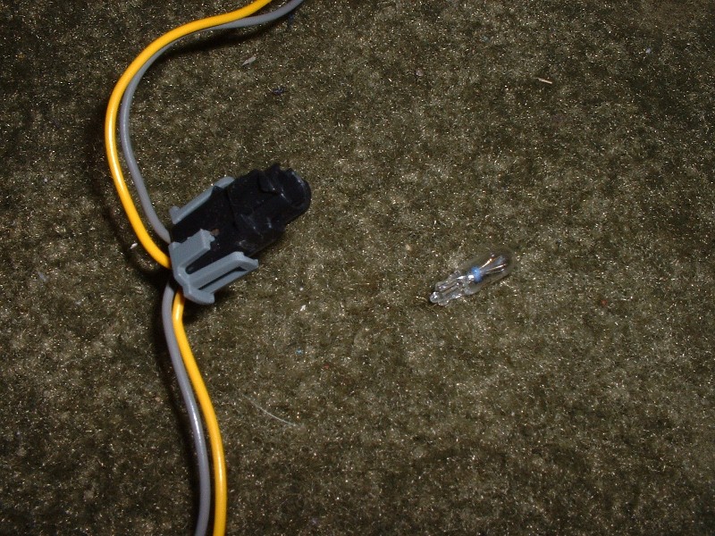
Remove the bulb sockets from the panel. Turn counter-clockways about a quarter turn, then remove.
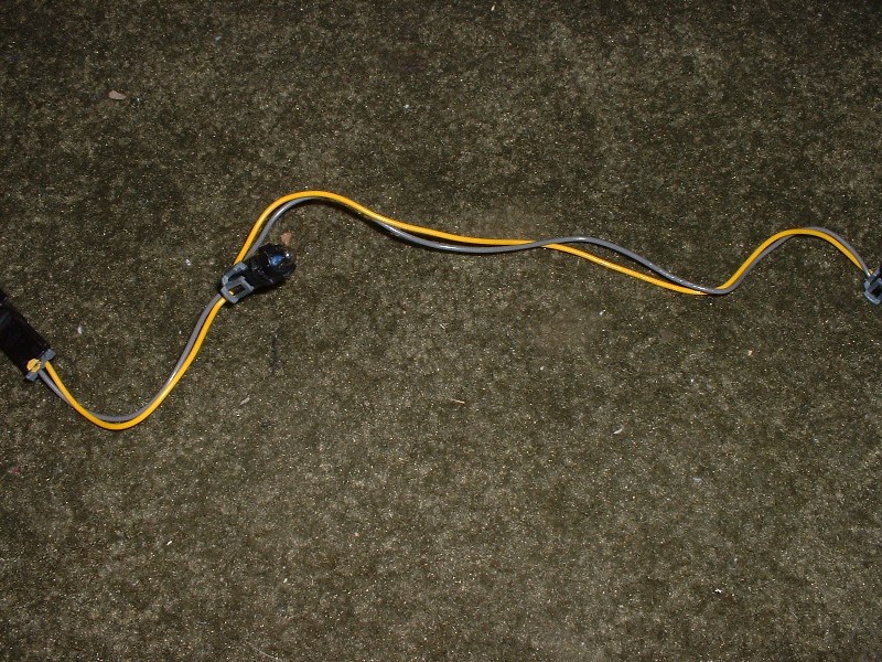
Step 2
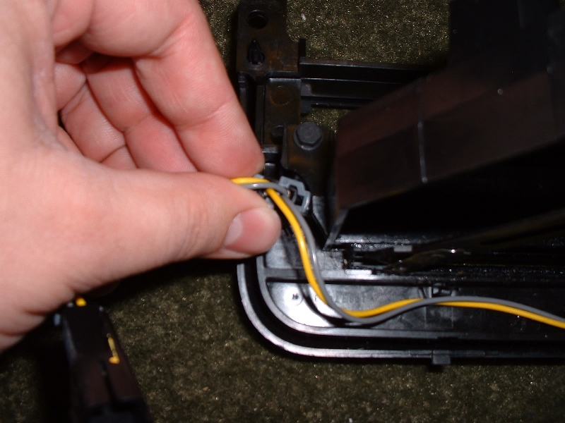
Remove the wires from the panel. Just pop them free from the two clips along the bottom of the panel.
Step 3
Remove the bulbs. They’re tight, but they just pull straight out.
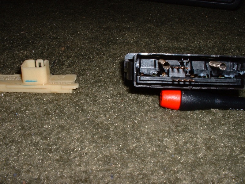
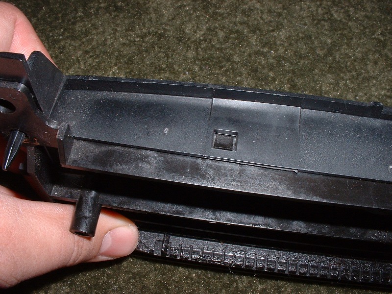
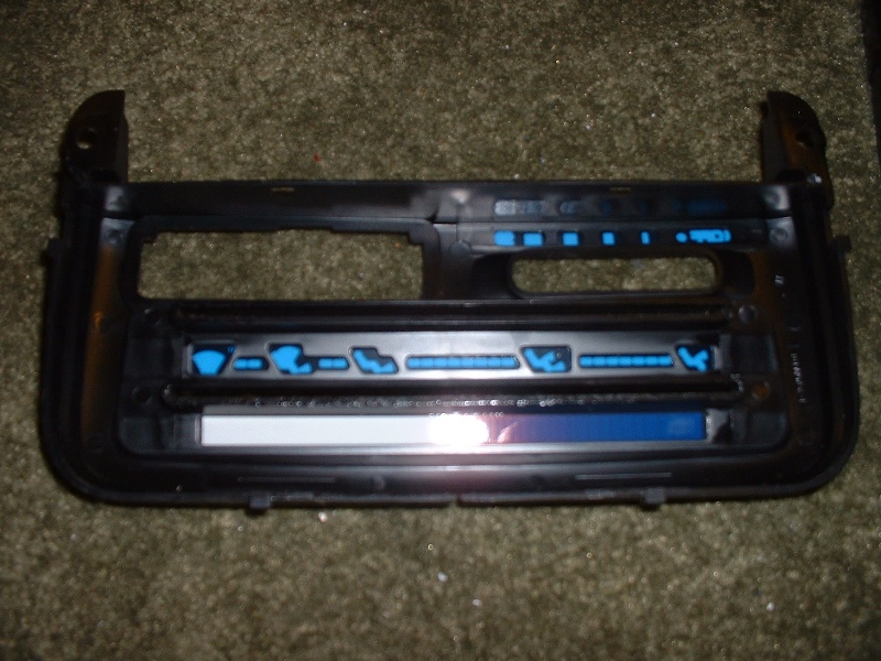
Dismantle Temperature & Vent Selector Sliders/Cable Controls
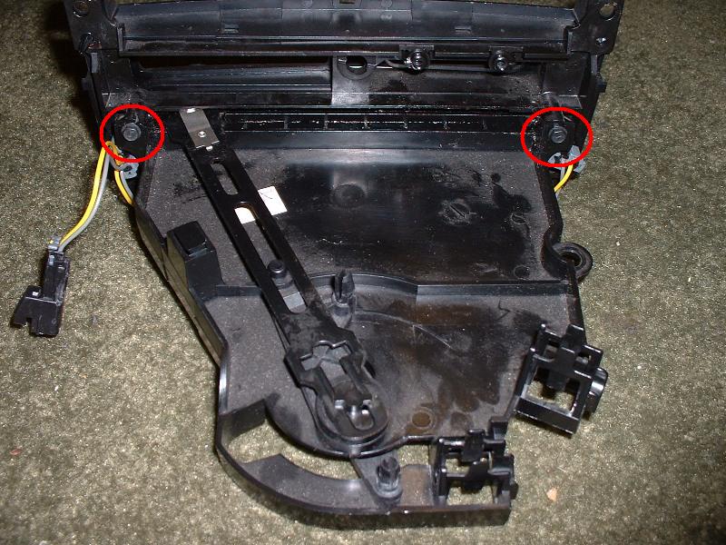
Step 1
Remove two screws. 1/4″ screws.
Step 2
Pull on control face to pop slider knobs loose. Shouldn’t take too much force, and it’s easier than trying to pull/pry on the knobs themselves. At this point the whole control face should come off.
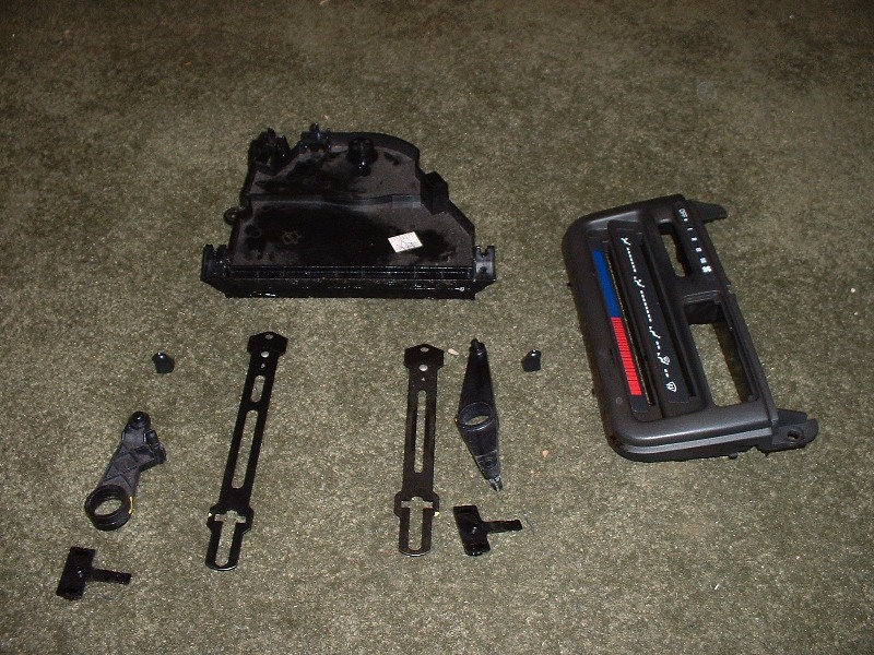
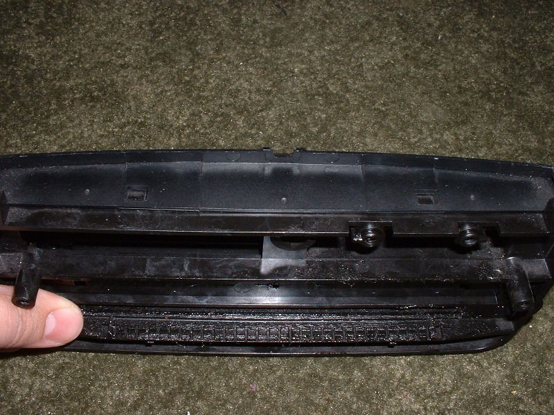
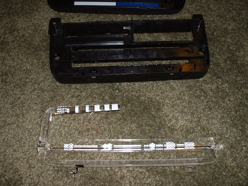
Step 3
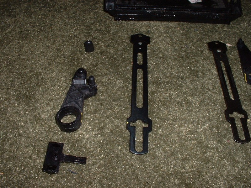
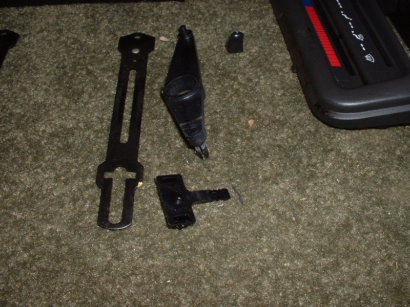
Dismantle cable controls. The metal bars will free up if you line them up with the center of the slider motion, and back slightly (pay attention to the notch at the pivot point). With the bar off, the plastic piece underneath will come free (the one on the underside has to be rotated to one extreme position to line it up with an opening and remove). The piece the knob came off of will also lift off at this point, but will probably stick in place because of lubricant.
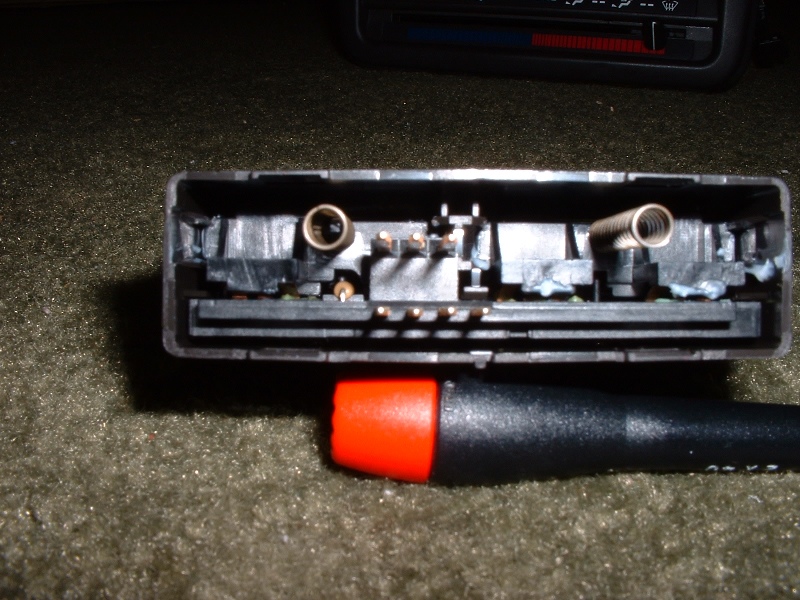
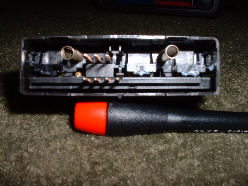
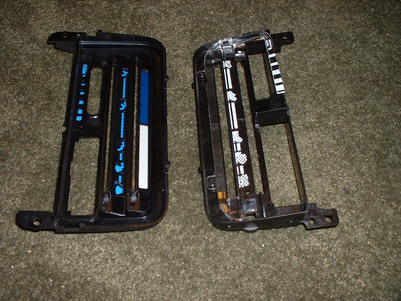
Reassemble Temperature & Vent Selector Sliders/Cable Controls
Step 1
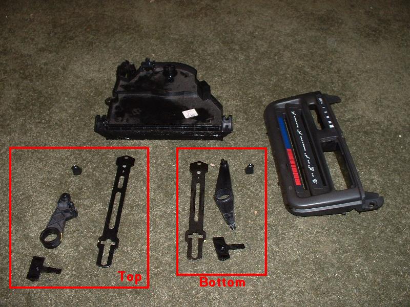
Reassemble cable controls. For both the top and the bottom, place the plastic pivot piece and plastic slider on first, then the metal bar. The metal bar goes on with the slider end having the silver springy piece away from the slider. See picture below for which parts go on top and bottom.
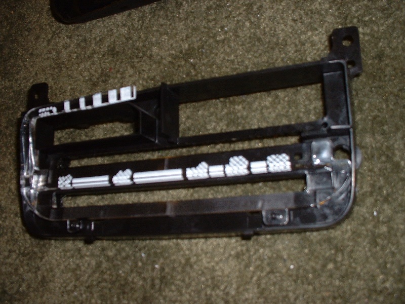
Step 2
While holding the cable controls together, slide the controls back through the HVAC controls face. Reinstall the knobs for the sliders to hold everything together.
Step 3
Reinstall 2 screws. 1/4″ screws.
Reassemble Temperature & Vent Selector Sliders/Cable Controls
Step 1
Use a flathead screwdriver to pop 2 tabs on top free. Then pull the face back from the face front.
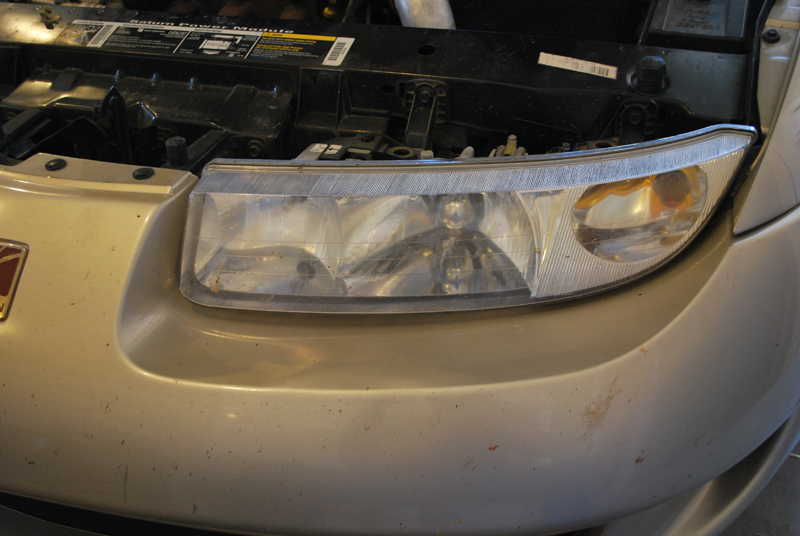
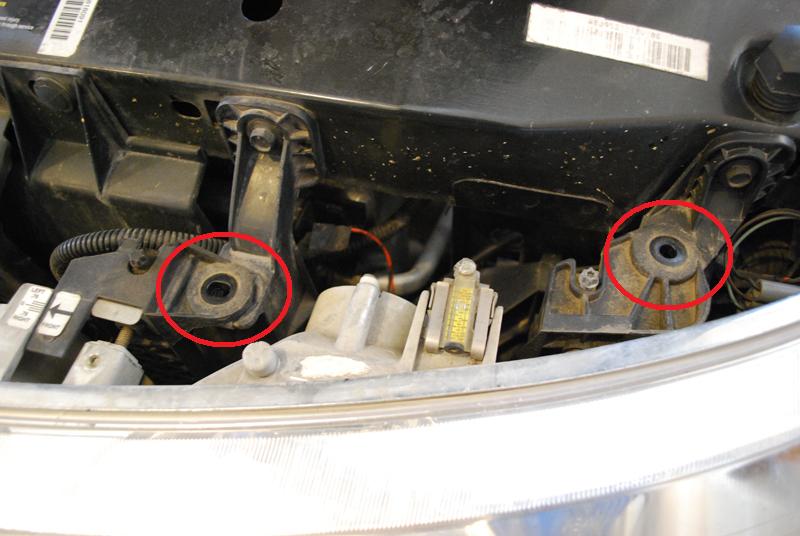
Lift the headlights, then move them forward. The bottom of the headlight bracket rests in a notch, so the assembly has to be lifted before being pulled forward.
Step 3
Remove the bulbs from the headlight assembly. The headlight bulbs twist about 1/4 turn to line up tabs and pull straight back to remove. The turn signal bulb has a tab that has to be depressed before twisting and removing the bulb.
Lower the steering column. There are 2 bolts holding steering column up to the dash substructure. Remove them, and lower your steering column, letting it rest on your seat.
Step 4
Unclip the wiring harnesses. There are 2 wiring harnesses attached to the back of the gauge cluster. Squeeze the tabs on the sides of the harnesses to release them from the cluster. They’re tight, so it will take a strong squeeze, or you can pry at them with a flathead screwdriver.
Step 5
Remove the cluster surround. There are two 2-piece clips holding the surround/bezel in. Push the center circular pin in slightly, then pry gently out to remove both parts of the clip. You may be able to get it to pop out by pulling gently at the surround. Once the two clips are out, the surround should come out.
Step 6
Remove the cluster. At this point, nothing should be holding the cluster in, and there should be enough clearance with the steering column dropped to remove the cluster.
Unclip the switch.Use your screwdriver to unclip the front & back ends of the switch, and pry downward slightly. It doesn’t take much force. Once both sides are free, carefully pull the switch downward, working the wires along with it.
Step 3
Unhook the wiring harness.The harness is held on in one spot. Use your screwdriver to lift the clip out of the way, and pull the wire harness out. The switch should now be free.
Installation
Step 1
Plug in the wiring harness. It is keyed, so it cannot be plugged in incorrectly.
Step 2
Push the switch into place. The wiring harness will point to the passenger side. The switch should click right into place.
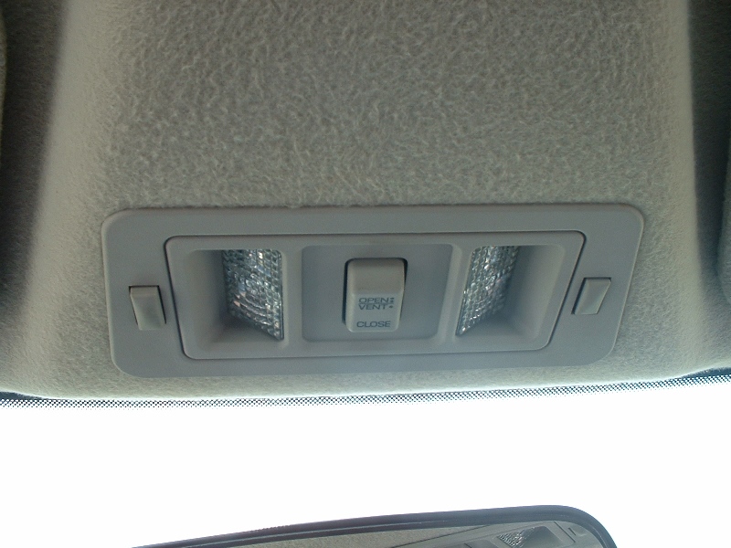
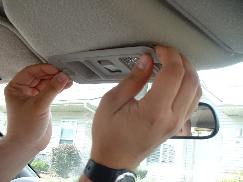
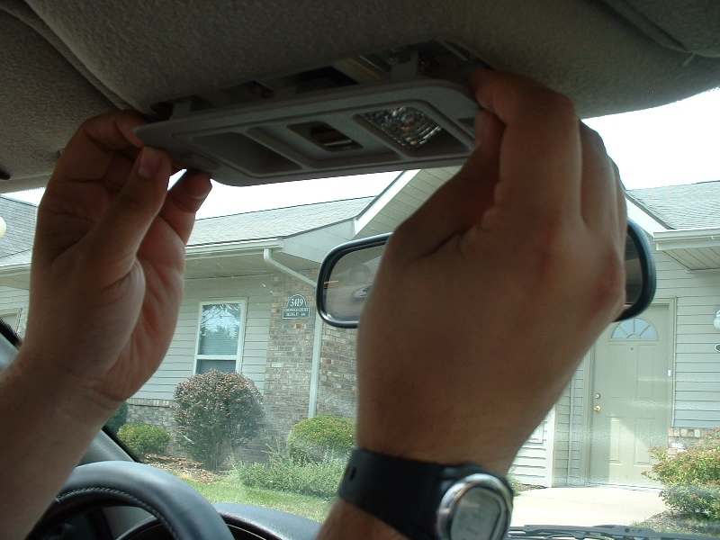
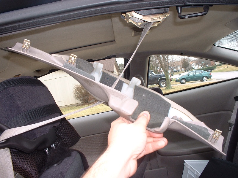
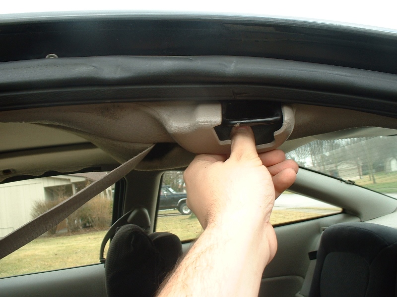
Gently but firmly pull down near a corner of the trim, then work around. The trim is snapped on near each corner (four snap points), but there is no way to remove the trim other than pulling it down or removing the whole headliner, which is very time consuming. There might be a slight risk of plastic breaking if it is very old, but it doesn’t seem likely.
Installation
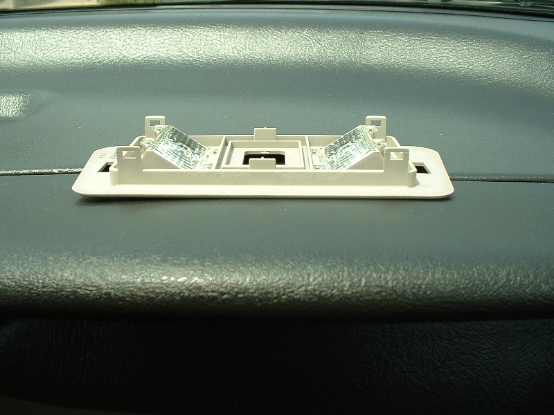
Line it up and snap it in. The wider part of the trim goes toward the front of the car. Just line up the snaps, or the map light buttons, and push it up to snap it in place.
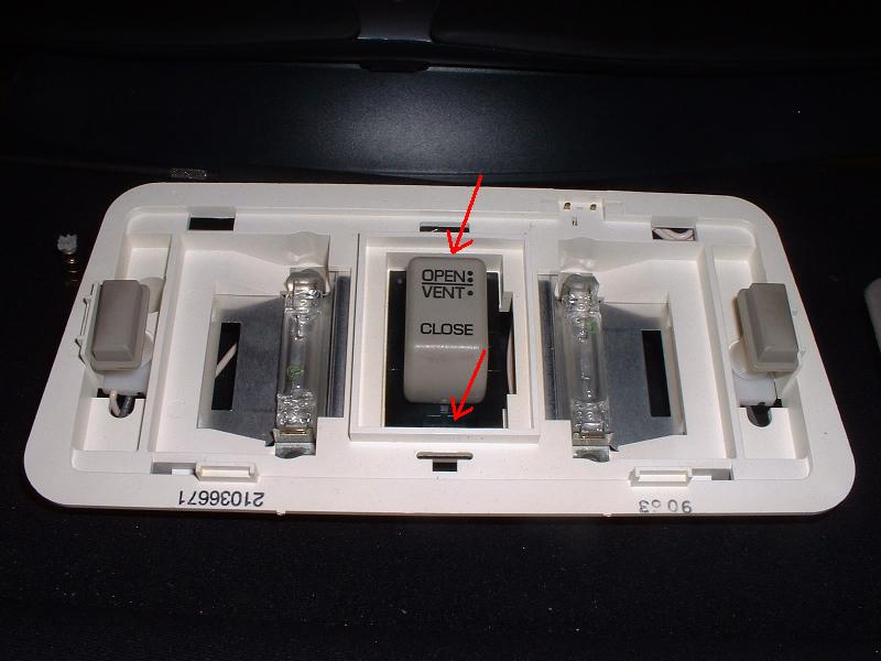
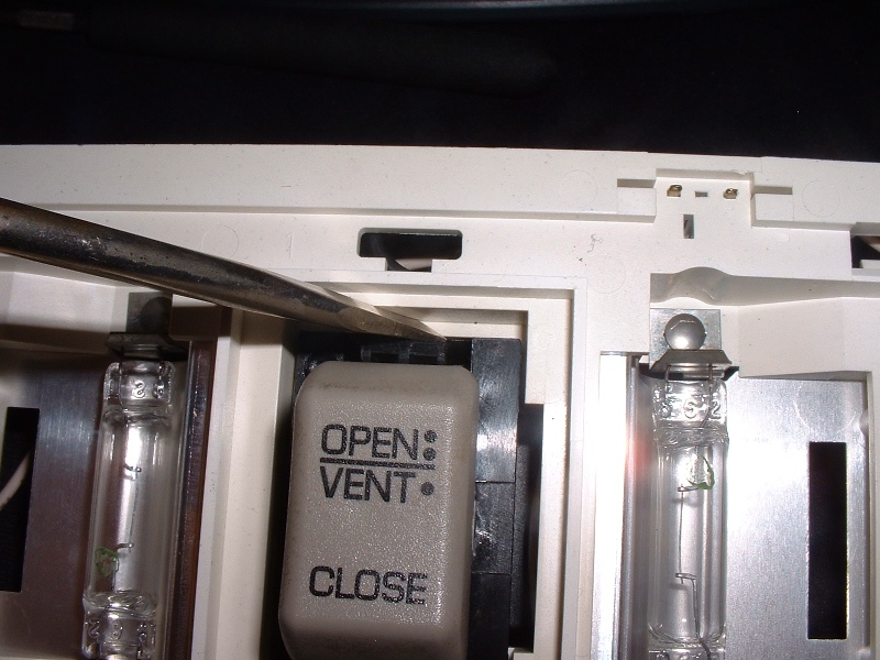
Remove switch cover. The switch cover pivots on 2 points, you’ll have to carefully pry the switch away from & over those two points.
Step 4
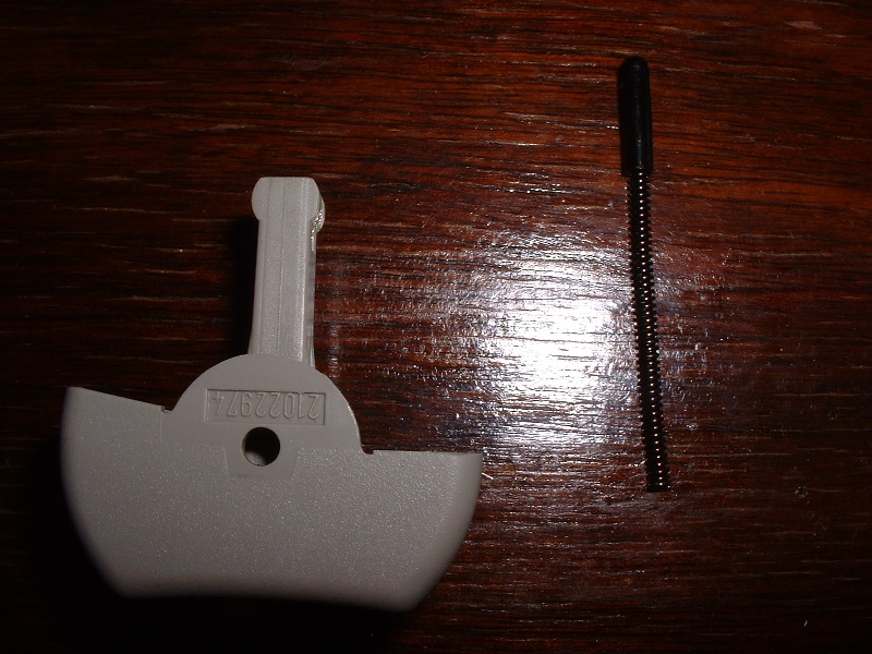
Remove the spring and black cap. They slide right out. I recommend keeping them someplace you can find them in case you want to undo this mod.
Step 5
Reassemble
Explaination
The spring and cap are what causes the switch to return to the center position. By removing them, you can put the switch in any position and leave it.
Warning
You need to be sure to put the switch back in the center (neutral) position after the sunroof opens or closes. It is likely that the sunroof stops moving simply because it cannot move anymore when it gets to the end positions, but the motor is still receiving power. Leaving the switch in the open/close positions after motion may damage the sunroof motor, and Saturn sunroofs are not fun to repair. This mod should not, however, risk running your battery down if left in an open/close position, because the sunroof switch does not receive power unless the key is in the “run” position.
Sorry, this is just a placeholder post – we need someone to build this guide! Click the button above if you’d like to contact us about building & submitting this guide.
If you have a Saturn S-Series that was made before mid 2001, you should probably replace the ECTS in your car as a preventative measure. Before that year, Saturn used a resin-tipped ECTS, then they switched to a brass-tipped one. The resin tip will inevitably split, and the sensor will go bad, and may even allow some small amounts of coolant leakage, causing corrosion on the wiring harness for the ECTS. For a $10-20 part, and to avoid all the problems that come with a bad ECTS, it is worth replacing, and it’s easy.
*’91-’95 owners* You have two temperature sensors in the area. The two-wire one is the ECTS that sends to the PCM. The other sends to your instrument cluster.
The ECTS is a thermistor – that is, it’s a resistor that changes resistance with temperature. The resistance level tells the PCM the coolant temperature. The ECTS and the IAT (Intake Air Temperature) are the same part.
This is a good thing to do while you’re at it if you need to replace your thermostat, or anything else that drains the coolant. You do not, however, need to drain the coolant to replace the ECTS.
<< sensor end wiring connector end >>
Relevant Models
All S-Series
Tools
8mm, 13mm sockets & ratchet
Needle nose pliers (angled tip if you have them)
Rag (don’t worry, you won’t have to use it much at all if you follow directions)
Parts
New ECTS (brass-tipped. You can get this at the dealer, or a parts store. Some parts stores still have the resin-tipped ECTS, so look before you buy)
New ECTS wiring connector (Optional) Sometimes a bad ECTS allows coolant onto the connector, causing corrosion. If this happens, you need a new connector. If not, you probably don’t. If a place stocks one near your house, might wait. If it’s going to be a show stopper and keep you from getting to work, you might go ahead & get it, and either replace it whether or not it needs it, or return the part if you don’t need it.
If you have trouble finding the connector, you can pull the pigtale for the intake temp sensor from a salvage yard vehicle. It’s the same connector, but doesn’t get the exposure to moisture that the ECTS connector can, so they’re usually fine.
Preparation
Necessary:
Let the car sit until the engine is COLD. Not cool, cold. Overnight cold. If it’s warmed up at all, you will lose a lot more coolant.
Disconnect the negative battery cable.
Helpful:
Jack up the driver’s side of the car.This will help reduce coolant loss.
Remove the battery.You have to remove the negative battery cable anyway, and this will give you extra working space. Requires the 8mm socket.
Remove the coolant reservoir cap, then put it back on. This relieves pressure on the coolant system so when you pull the ECTS, the pressure doesn’t push more coolant out. Putting the cap back on helps hold the coolant in.
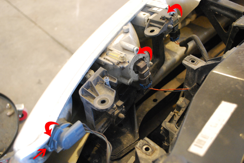
Step 3
Remove the wiring connector from the ECTS. If you have needle-nose pliers with an angled tip, those work really well, but any needle nose pliers will work, or possibly even your hands. Squeeze on the two sides to release the connector. The connector locks in place, so don’t pull on the wires – it will only hurt things.
Step 4
Inspect the wiring harness. If it has any corrosion, replace it.
Step 5
Remove the ECTS. Use the 13mm socket, and rotate counter-clockwise (normal thread). A little bit of coolant will come out (not even a spoon-full when I did it). Have a rag and the new sensor ready.
Step 6
Quickly but carefully, put the new sensor in. Don’t over tighten, it doesn’t take a lot of force. (I’ll try to find the torque standard for it and add it here.)
Step 7
Reassemble. Snap the wiring connector back on the ECTS, put back on everything else. You’re done!